Tube Piercing
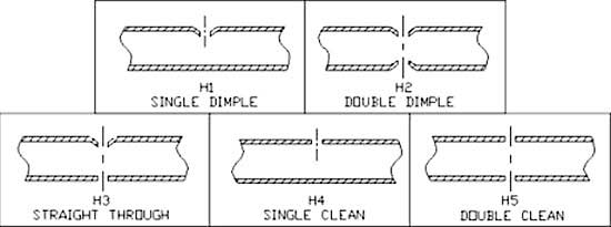
Multicyls are used for many types of tube pierce applications. The following chart illustrates the 5 most common. Scroll down for details on each of them.
Multicyls are used for many types of tube pierce applications. The following chart illustrates the 5 most common. Scroll down for details on each of them.
Multicyls are used for many types of tube pierce applications. The following chart illustrates the 5 most common. Scroll down for details on each of them.
H1 Single Dimple & H2 Double Dimple Hole Applications
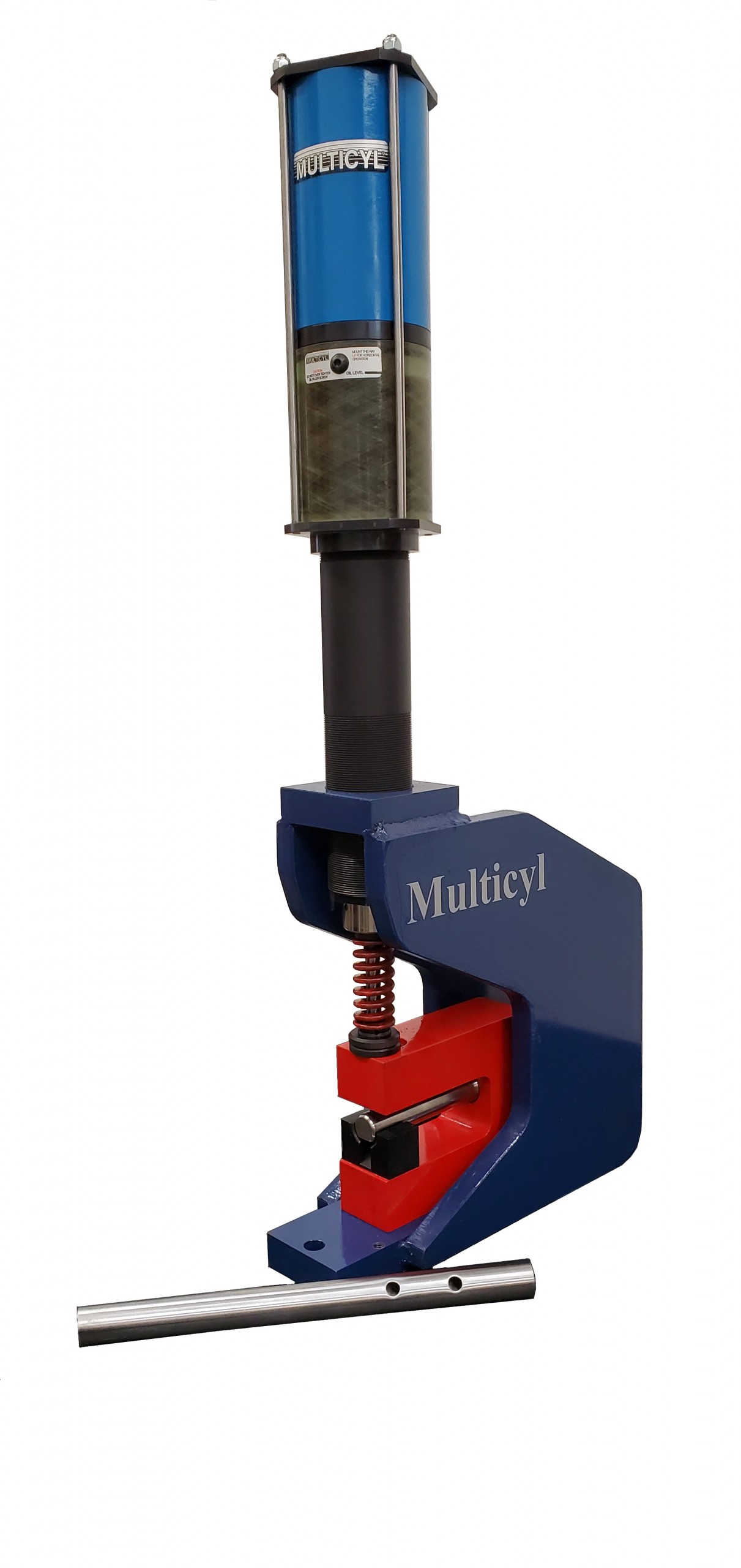
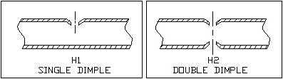 Multicyl offers a range of standard tube pierce stations for H1 and H2 punching systems, one of our most popular applications. Standard systems accommodate round or shaped parts up to 1.5” in size. Custom larger systems may also be quoted upon request. Front feeding of the tube makes it possible to pierce parts after forming. The tooling uses upper and lower guides which encapsulate the tube to prevent OD distortion. Guides and punches are easily interchangeable to allow a single unit to perform various applications. An H1 system is easily converted to an H2 system by adding a punch assembly to the bottom guide. H1 and H2 tube pierce stations are the most cost effective method of punching holes in tubing.
Important information when requesting a quote for this application includes: tube diameter, material and wall thickness, hole diameter, hole location, and application number (H1 or H2). A drawing is always best to quote from.
H3 Straight Through Hole Applications
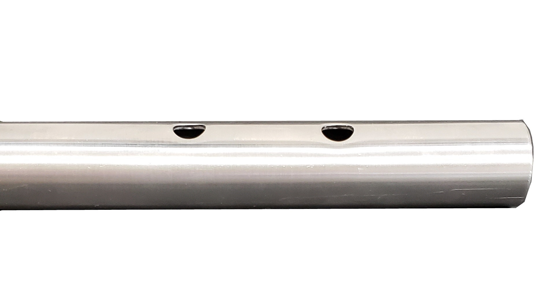
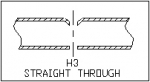 Multicyl straight through tube pierce stations produce a through hole which is dimpled on the top and clean (no dimple) on the bottom.
H3 stations are similar to their H2 counterparts except that rather than housing a second punch the bottom guide contains a die button to produce the clean bottom hole as the punch is powered straight through from the top.
 Maintenance may be higher with this application as the punch tip is significantly longer and the bottom hole is actually punched with the slug from the top hole. Because of the longer distance that the punch must travel in this application longer stroke cylinders are used and applications are limited to tubes with 1.00” maximum diameter (front feed) or 1.25” maximum diameter (side feed).
Important information when requesting a quote for this application includes: tube diameter, material and wall thickness, hole diameter, hole location, and application number (H3). A drawing is always best to quote from.
H4 Single Clean
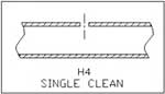
H4 holes are another of our most popular applications. Multicyl offers a range of semi standard mandrel punching systems for this application.
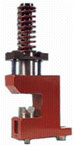
Unlike the H1, H2, and H3 systems, there are no external guides in the H4 tooling. Instead an internal mandrel is used to support the inner wall of the tube. The mandrel contains a die button which is used to produce a clean hole similar to standard flat material hole punching.
 There is almost no limit to the tube size for H4 mandrel systems. However, because the tube must be front fed over the mandrel, the hole position must not be after any bends or OD reductions. Important information when requesting a quote for this application includes: tube
diameter, material and wall thickness, hole diameter, hole location, and application number (H4). A drawing is always best to quote from
H5 Double Clean
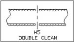 Multicyl offers three types of H5 systems:
- The first is the index method. This type of system uses a tool very similar to that employed in the H4 method with the only difference being the addition of a location pin. The tube is punched, indexed 180 degrees, located with the pin, and punched again.
- The second type of H5 Multicyl system, which is quickly becoming one of our most popular products, is the double horizontal mandrel system. This system uses a unique set-up of opposing Multicyls. The cylinders are cycled simultaneously, each powering a punch into a custom designed mandrel tool producing
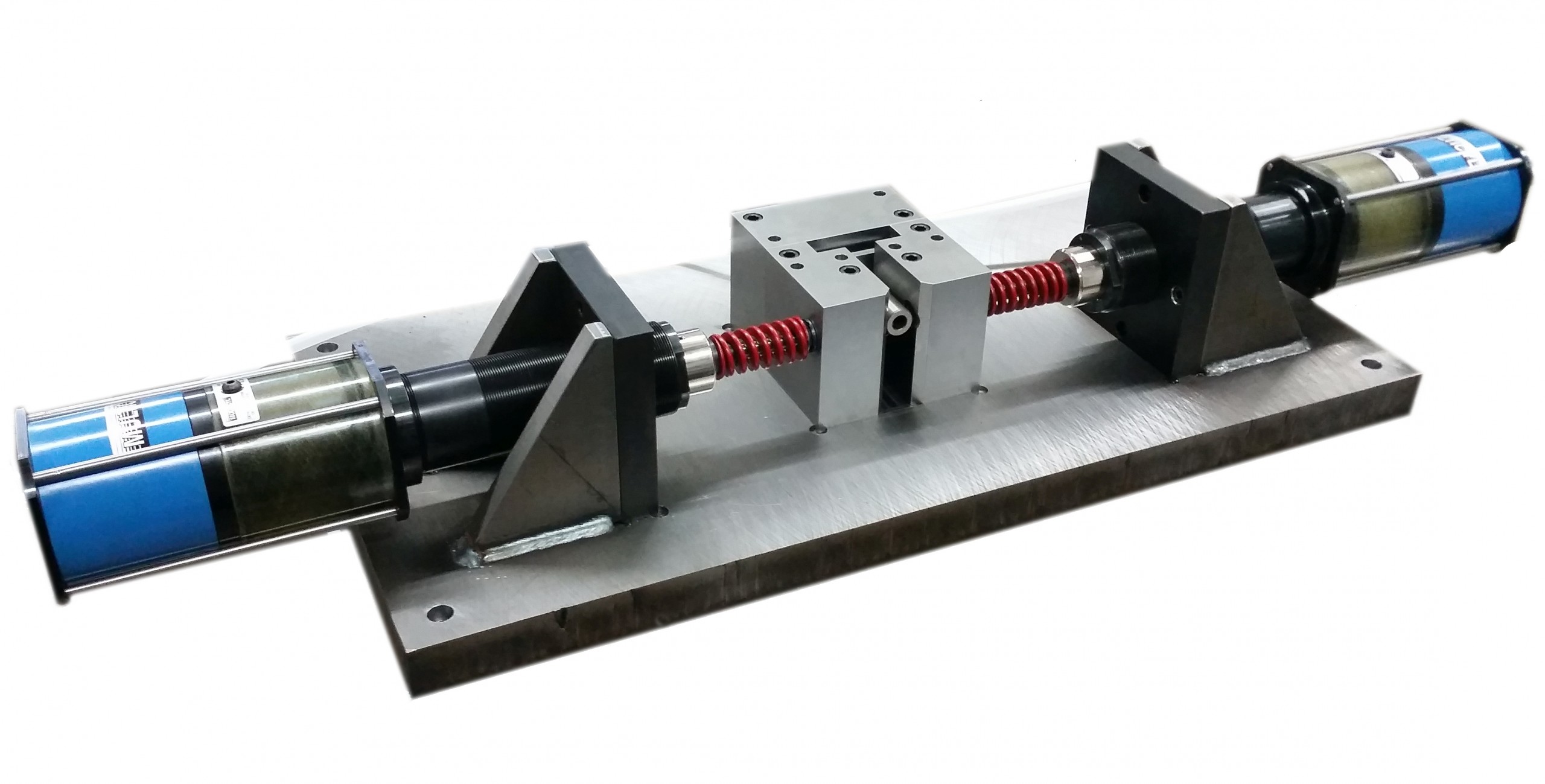 the through hole in one cycle. The slugs either fall through a slug chute in the bottom of the mandrel or are blown out a relieved section in its front. This is the best combination of efficiency and safety to be found in producing a clean through hole.
 - The third method is the straight through method, similar to H3 applications. This method uses a long stroke cylinder which powers a punch through the mandrel and into a second die below the tube producing the through hole. This method, however, involves the same maintenance and tube size limitations as with H3 applications. Using the short stroke cylinders employed in the first two options is desirable because they eliminate pinch points, reduce the tool wear and maintenance problems of the straight through method, and can produce cycle times as low as one cycle per second.
Important information when requesting a quote for this application includes:
A drawing is always best to quote from.